About Me
Welcome to my blog! This is where I collect my observations and notes on programming and technology. The main subjects range from implementation details to broader ideas about programming.
Main Topics
- Engineering Projects: Exploring implementation details and how technical systems work.
- C/C++: Notes on language features and programming techniques.
- The Programmer’s Perspective: Ideas about developing a career and a way of thinking as a programmer.
For more, visit the categories page.
Contact
If you have questions or would like to discuss something, please get in touch through the About page.
Thank you for reading and for your support. I hope these notes help you on your own technical journey!
Introduction
An interrupt or exception transfers control to a handler in response to an event. This is more specific than the general ability to jump to another instruction address. These notes examine internal events, external requests, the 8086 vector table, and the BIOS/DOS routines built on that mechanism.
Where events originate
An internal condition, such as division by zero or a quotient that does not fit, is detected by processor execution logic. External devices signal requests through hardware interfaces. Maskable external requests are subject to interrupt-enable state.
The original notes ask how the processor physically creates an exception signal and leave detailed circuit design for future study. One clarification is useful: an external programmable interrupt controller is not required to detect a divide error inside the CPU. Those are different event paths.
From a vector number to a handler
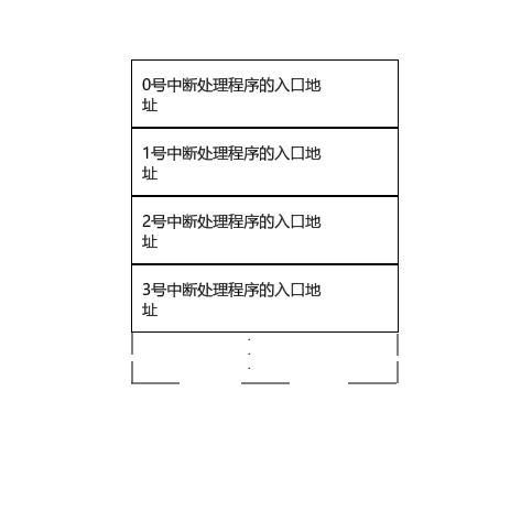
In the original 8086 real-mode arrangement, the interrupt vector table occupies physical 00000h through 003FFh: 256 entries of four bytes each. An entry stores a 16-bit instruction offset followed by a 16-bit code segment.
For vector n, the CPU reads the offset from address 4*n and the segment from 4*n + 2. These expressions locate the stored pointer; they are not themselves the values loaded into IP and CS. The processor transfers to the handler addressed by that pointer, rather than executing the table bytes as instructions.
For interrupt entry, the CPU saves the required return state on the stack, including FLAGS and the return code address, and adjusts interrupt/trace state. IRET restores the corresponding return state. Exact saved-PC behavior for exceptions depends on the processor generation and exception class.
Vector zero is associated with divide error. Executing int 0 explicitly invokes that vector too, but software invocation and an actual division fault need not have identical fault/restart semantics.
A familiar DOS service sequence is:
1 | mov ax,4c00h |
AH = 4Ch selects process termination and AL = 00h supplies its return code. The original 4chh spelling is a typo.
External devices and I/O ports
Interface cards, motherboard controllers, and devices such as CMOS/RTC hardware expose registers through their interfaces. Depending on the architecture and device, those registers may be memory-mapped or placed in a separate I/O space. x86 supports distinct I/O-port instructions.
In the historical PC keyboard arrangement, the controller exposes data at port 60h and requests service through IRQ1 and the interrupt controller. The external controller and the keyboard’s own scanning electronics have different roles.
Reading and writing ports
1 | out 60h,al |
IN moves data into the accumulator; OUT moves it out to a port. This direction explains the operand order. For the discussed 16-bit forms, AL transfers a byte and AX transfers a word.
Correction: the source associates AL with ports below 256 and AX with higher ports. Data width does not determine port-number range. An immediate encodes a port from 0 to 255; DX supplies a port number from the wider 16-bit space. Either permitted data width can be used with the appropriate form.
Why interrupts can be masked
Masking temporarily prevents delivery of ordinary maskable requests. This can protect a short critical update, avoid unwanted nesting, or maintain priority while handling another event. It does not necessarily erase a pending device request.
Stack initialization is an instructive example:
1 | mov ax,0200h |
The SS and SP updates belong together so an interrupt does not use an inconsistent stack. x86 provides a specific interrupt-inhibition window after loading SS; this should not be generalized into a claim that all possible events are excluded or that arbitrary multi-instruction updates become atomic.
Keyboard IRQs are maskable. NMI arrives through a separate mechanism and is not controlled by IF. It is often associated with urgent hardware conditions, though it can also serve other purposes such as debugging. Interrupt priority depends on the processor and controller rules.
IF, STI, and CLI
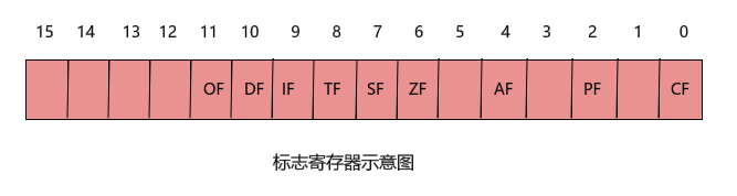
IF is the interrupt-enable flag for maskable hardware interrupts. STI sets it and CLI clears it, subject to the execution mode’s privilege and timing rules. Software interrupts and synchronous exceptions are not simply disabled by clearing IF. Not every instruction changes every flag.
Vector numbers and ownership
An eight-bit vector number has 256 possible values, zero through 255. Later x86 architectures reserve the low range for architectural exceptions, while historical PC firmware and DOS use conventions that can overlap differently. Apply the rules for the actual generation and environment.
The source identifies 0000:0200–0000:02FF as unused space for an exercise. That is not a universal guarantee: this region contains vector entries, and installed software may use them. A real installation must preserve or allocate vectors appropriately.
Familiar internal and software-triggered events
- Vector 0: divide error.
- Vector 1: debug/single-step facilities, used by debuggers to regain control.
- Vector 3: breakpoint, commonly generated by the dedicated breakpoint instruction.
- Vector 4: overflow when
INTOexecutes with OF set in supported legacy modes.INTOis unavailable in 64-bit mode; calling it generally obsolete because of performance is not the precise distinction. INT n: an explicit software request to invoke vectorn.
Software and hardware interrupts differ in their trigger. A program executes INT; an external device raises a request. The handler entry mechanism can still share a vector-table organization.
BIOS boot and handler installation
For the original 8086 reset model, execution begins at FFFF:0000, physical FFFF0h, commonly containing a jump into firmware. Later x86 reset details differ. Firmware performs hardware initialization and installs its service vectors. A legacy bootstrap routine then selects a boot device, loads an appropriate boot sector, and transfers control to a loader that brings in the operating system.
BIOS is firmware stored in ROM or flash, not ordinary writable RAM. The original suggestion of simply rewriting instructions at FFFF:0000 requires a suitable firmware or emulator modification mechanism; a normal memory store does not generally accomplish it.
BIOS int 19h
This is the familiar legacy bootstrap service. It should not be assumed to be literally the first interrupt firmware ever invokes during initialization.
BIOS int 10h: video services
Function 2 sets the cursor position:
1 | mov ah,2 |
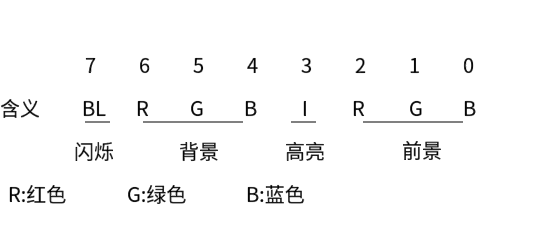
This selects page zero, row five, column twelve. Function 9 writes a character and attribute:
1 | mov ah,9 |
The example requests three copies of L with attribute seven. Many BIOS and DOS services select a function through AH, but that is an interface convention to check for each service, not an invariant of all interrupts.
BIOS int 13h: disk services
The traditional CHS interface addresses cylinders, heads, and sectors. Cylinder and head numbering starts at zero; sector numbering starts at one. The source’s two-head description fits a particular disk geometry, not every device.
1 | ; ES:BX points to the destination buffer. |
This requests one sector using the indicated drive and CHS values. Function 3 writes instead of reading, with ES:BX pointing to source data. Real code must respect geometry, buffer limits, and the returned status; the snippet illustrates parameter placement only.
BIOS int 9h: keyboard IRQ handling
In the legacy mapping considered here, IRQ1 invokes the keyboard handler at vector 9. Keyboard scanning electronics detect key transitions and send scan codes to the host controller. The host controller makes data available at port 60h and requests an interrupt.
For many ordinary keys in scan-code set 1, pressing produces a make code and release produces the make code plus 80h. Extended keys and other scan-code sets have different sequences, so this is not a universal keyboard encoding rule.
The source’s make-code table, expressed with standard key names, is:
| Key | Code | Key | Code | Key | Code | Key | Code |
|---|---|---|---|---|---|---|---|
| Esc | 01 | U | 16 | H | 23 | B | 30 |
| 1–9 | 02–0A | I | 17 | J | 24 | N | 31 |
| 0 | 0B | O | 18 | K | 25 | M | 32 |
| Minus | 0C | P | 19 | L | 26 | Comma | 33 |
| Equals | 0D | Left bracket | 1A | Semicolon | 27 | Period | 34 |
| Backspace | 0E | Right bracket | 1B | Quote | 28 | Slash | 35 |
| Tab | 0F | Enter | 1C | Backtick | 29 | Right Shift | 36 |
| Q | 10 | Ctrl | 1D | Left Shift | 2A | Keypad asterisk | 37 |
| W | 11 | A | 1E | Backslash | 2B | Alt | 38 |
| E | 12 | S | 1F | Z | 2C | Space | 39 |
| R | 13 | D | 20 | X | 2D | Caps Lock | 3A |
| T | 14 | F | 21 | C | 2E | F1–F10 | 3B–44 |
| Y | 15 | G | 22 | V | 2F | Num Lock | 45 |
| Scroll Lock | 46 | Keypad minus | 4A | End | 4F | Delete | 53 |
| Home | 47 | Left | 4B | Down | 50 | ||
| Up | 48 | Right | 4D | Page Down | 51 | ||
| Page Up | 49 | Keypad plus | 4E | Insert | 52 |
Navigation and Print Screen interpretation can involve prefixes and keyboard layout/state; the compact table does not describe every sequence.
The handler reads the scan code, updates modifier/toggle state, and places suitable character events into the BIOS keyboard buffer with their corresponding character codes. A traditional state byte is located at 0040:0017. A custom handler can replace or chain this behavior when installed correctly.
BIOS int 16h: consuming keyboard input
The hardware handler fills the buffer; an application still needs to read it. Function zero waits for a key event:
1 | mov ah,0 |
It returns the scan code in AH and the corresponding character code in AL for the applicable event. Conceptually, the routine waits while the queue is empty, retrieves its oldest entry, and advances the queue. The traditional sixteen-word circular buffer commonly leaves one slot unused, allowing fifteen queued entries.
Keyboard state
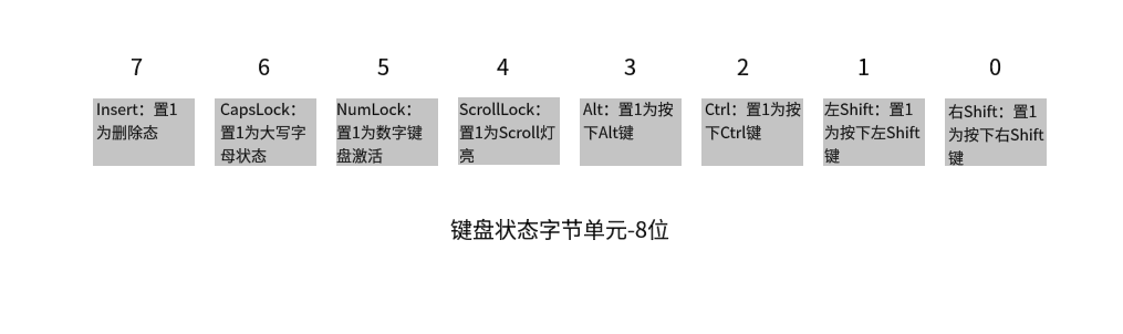
Modifier and toggle keys affect state, although particular key combinations can also generate buffered events. The original article included a ChatGPT explanation of Scroll Lock: historically it influenced scrolling behavior, and some applications still assign it a role. In spreadsheets such as Excel, it can make arrow keys scroll the worksheet instead of moving the selected cell. Behavior is application-specific; consult the application’s documentation rather than assuming one global action.
DOS services
int 21h, function 4Ch
1 | mov ah,4ch |
This terminates the DOS process with return code zero.
int 21h, function 9
1 | ; DS:DX points to a dollar-terminated string. |
This displays a string ending with $, allowing the program to use a DOS service instead of writing directly to video memory. The service’s terminator differs from the zero-terminated strings used in other examples.
For architectural interrupt details across later x86 modes, consult the Intel system programming manuals. The BIOS and DOS conventions above belong to the historical environment described in this article.
If you like this blog or find it useful for you, you are welcome to comment on it. You are also welcome to share this blog, so that more people can participate in it. All the images used in the blog are my original works or AI works, if you want to take it,don't hesitate. Thank you !